<< PREVIOUS: Hardware: Parts List —————————————————————— NEXT: Software: Tracking >>
*********************************
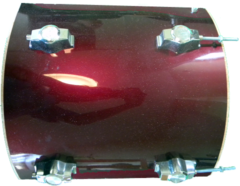
1) The first step is to cut the drum in 3 parts. The reason to do this is two-folded. On the one hand it needs to have one third of it completely open so as to let the camera see the shape of the spandex head when it deforms and the second is to make a device with which one can travel. If you bought a 14 inch drum, the circumference is about 44 inches. I cut mine in three sections of around 16, 15.5 and 12.5 inches. I left the 15.5 inch section out as the open section. In figure 1 you can see one of the sections.
The drum you bought should have included the body of the drum and two metal rims with their respective screws. It will also probably come with one or two drum heads which we will not use.
.
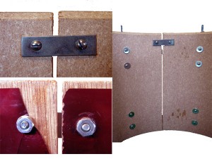
2) the next step is to make two small holes (that coincide with the metal piece of fig 6 in the parts list) at the top, or what we want the top to be, so that they can be held together as seen in figure 2.
Attach them together with two screws and bolts. You can put some washers there if you want.
We should now have 2/3rds of a drum.
.
.
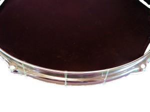
3) Now we need to attach the lower rim to the 2/3rds of a drum we achieved in the previous step.
Use the rim and screws that came with the drum. The drum key will come in handy for this part. It should look like Figure 3. Note the rim is upside down. Regularly, rims are used to stretch a drum head, we on the contrary, are using it to get the drum to be compact/solid/strong after cutting it in pieces.
.
.
4) The next step is to prepare the spandex head and the rim. I used two layers of spandex fabric and a thick elastic band. Choosing the spandex is not straightforward. I just went to a textile shop and chose one. The key is that it deforms easily, but recovers its flat shape very fast and doesn’t wear too much over time.
Form a circle with the elastic band, then saw a fold of the two layers of spandex over it and saw them as shown in figure 4.
After sawing the spandex, attach it to the top rim with the nylon (I use it because it is resistant, but you can use something else). Make sure that the spandex head is stretched at the lower level of the metal rim as seen in figure 5.
I’ll post new pictures when i get some time to build a new head.
.
.
5)
The top rim needs to be adjusted to the drum body. Use the cut rod and nut numbered 2 in fig. 4 of the parts list.
.
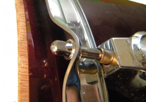
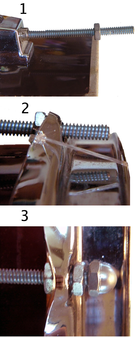
After screwing the rod into the body of the drum, use a nut to set the level at which the rim will rest as shown in figure 6.1.
.
Fit the rim in the rods until it rests on top of the nut as seen in Figure 6.2.
.
Then adjust the rim with the nuts and cap (shown in figure 5 of the parts list) as seen in Figure 6.3.
.
The lower part of the rim needs to be fixed at the level where the body of the drum ends. The result should look like Figure 7.
.
6)
Once the structure is built, we need to prepare for tracking.
Get the white cardboard (it should be a flexible and light reflective thick white paper).
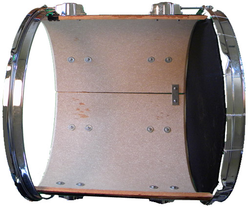
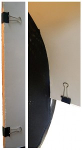
Cut it so as to cover all the interior of the drum.Once you have it cut, hold it to the body of the drum with paper clips as seen in Figure 8.
It is important to make sure that when you press the spandex, it doesn’t get stuck with the white cardboard/paper.
The result should now look like Figure 9.
7)
At this point the drum structure is ready.
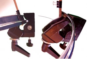
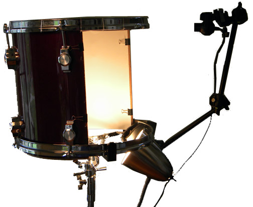
We now need to attach the clamp and arm. the clamp must be attached to the lower metal rim as seen in Figure 10. I put it to a side to allow visibility by the audience, but, it can be set at any part of the rim. It is crucial that the clamp does not move at all.
.
.
Once the clamp is tightly attached, we need to insert the arm into the clamp as seen in Figure 11.
The camera needs to be prepared in advance. Remove the base of that comes with the PS3eye camera. You can do this by removing the plastic covers that are on top of the screws, opening it up (carefully!), removing the base, and screwing it up again. You can see someone doing it in the embedded video below. We are not interested in removing the IR filter, just so you know how and what to expect when opening the camera without breaking it.
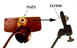
Use two nuts (that are the same size as the screw in the bracket) and stick them to the back of the camera. Use very strong glue, I use a strong weld. Superglue and the like won’t be enough.
The camera then should look like it does in Figure 12.
Finally the camera should be fixed by screwing it to the bracket. We’ll calibrate and position it correctly in the tracking software section.
.
.
8)
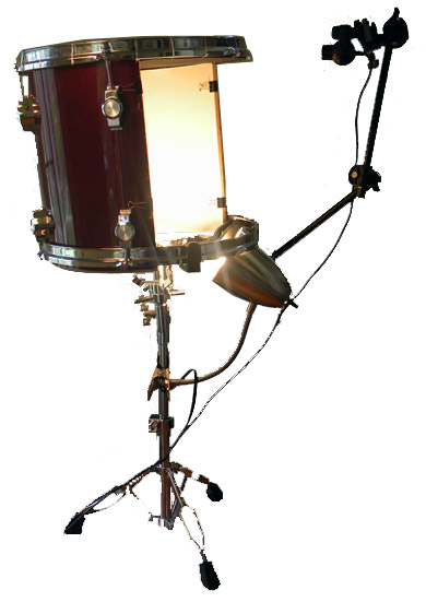
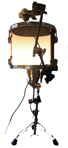
We can now attach the drum to the stand and attach the lamp to the stand as well and we have all the hardware in place. Below are some images.
<< PREVIOUS: Hardware: Parts List
<< PREVIOUS: Hardware: Parts List —————————————————————— NEXT: Software: Tracking>>



Pingback: HOW TO build a Silent Drum
Pingback: HOW TO build a Silent Drum: Parts List
Pingback: silent drum – tracking